- Joined
- Apr 18, 2011
- Messages
- 37
A few days after buying my Mille, the speedo sensor showed it's Italian heritage by croaking. The price of a new sensor seemed excessive to me (~£72) so I looked for an alternative solution, preferably one that would have a greater life expectancy and would be easier to source.
The original sensor is a biased hall effect device, i.e. a hall effect sensor combined with a permanent magnet. The output is a an open collector, i.e. the signal wire is grounded when ferrous metal is in front of the sensor, and is floating when no metal is present. The instrument pack pulls this wire up to around 9-10 volts, giving a 0-10volt swing. My sensor was still working to some extent, but the voltage swing was from 0volt to less than 1 volt (too low for the instrument pack to register) which indicates a high leakage current (probably moisture ingress).
I initially looked at cam sensors from car engines, some of these use the same kind of biased hall sensors. However, nothing I found fitted very well and they are still quite expensive if you buy a genuine part (and the after market parts can be quite short lived). So I started looking at industrial proximity sensors. These work on a different principal to the hall effect sensors; they create a high frequency magnetic field from a coil in the sensor. A conductive material brought near the coil will have eddy currents induced which oppose the generated field, effectively reducing the 'Q' of the coil. This is detected by the circuit within the sensor. The advantages of these sesnors are as follows:
1) They are made by numerous companies to standard sizes. Cherry, Omron, Turck, Seimens, Honeywell, Autonics, Rockwell are just a tiny sample of the companies that manufacture these sensors. This means easy availability, and low cost.
2) Robust. These sensors are designed for harsh industrial applications, normaly sealed to IP67 (fully waterproof) and resistant to harsh vibration and shock.
3) They do not require ferrous materials to operate. This may be of interest to those that want to use Titanium disc bolts etc. The operating range is reduced with non-ferrous materials however, and I'm happy with steel bolts so I've not tried this.
4) Most sensors have an LED built into the end of the body so you can quickly set up the sensing distance and confirm correct operation.
I used eBay to source a suitable sensor, as buying direct usualy requires an account, and if you go through Farnell, RS, Digikey etc. you pay a premium, though it's still a lot cheaper than an Aprilia sensor. The key parameters are the output interface, which must be "NPN", and the switching frequency. Often these sensors are used for static applications like machine guard interlocks, so they are not expected to switch frequently, and some sensors will only operate at 100Hz or less. At 170mph, the Mille rear wheel is turning ~38 times every second, and there are 6 disc bolts so we need the sensor to have a switching speed of at least 38*6=228Hz to cover the speed range of the bike. Fortunately there are numerous sensors available that will switch up to 800Hz or more.
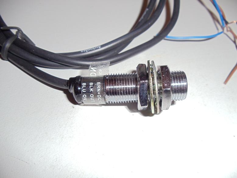
The sensor I bought is made by Autonics, and distributed through Hong Kong. Cost is under £5 inc. postage and it took about 10 days to get here.
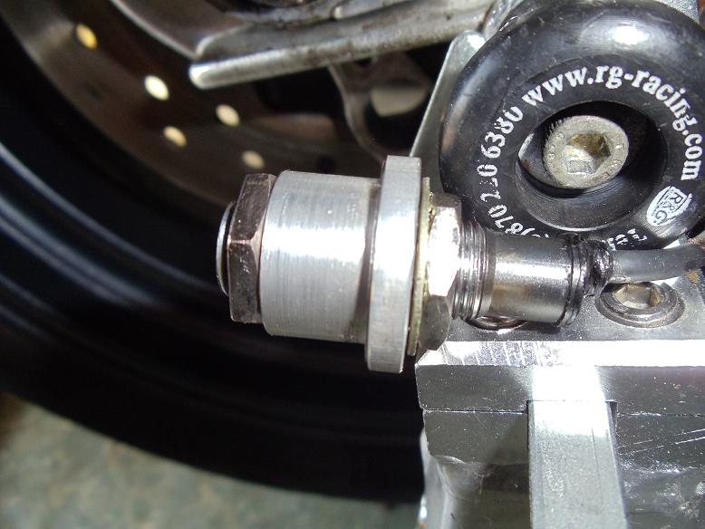
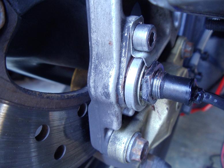
The main issue is how to mount the sensor in the caliper bracket. Having a lathe I turned up a simple top hat bush to hold the sensor, and fabricated a small spring steel clip to retain it. This is probably overkill however, a simple alloy, stainless or even plastic bracket could be used with an M12 hole for the sensor and an M6 hole for the retaining bolt.
The sensor:

The sensor installed in the bush:

The sensor installed in the caliper bracket:

I reused the connector from the old sensor, the wires need to be connected as follows:
The Autonics cable is thinner than the original Aprilia, so you can cut the original sensor off, tape the Autonics cable to the original and then use the original cable to pull the new one through. This saves a lot of messing around. Cut the connector of the original cable with 10cm or so of wire left, then join this to the Autonics cable, preferably a soldered connection with heat shrink to insulate and protect it.
I've not tested this absolutely flat out, but so far it works perfectly well into 3 figures. The sensor is rated to 800Hz which you'd have to be doing about 600 mph to achieve; even the mighty Mille would struggle with that
The original sensor is a biased hall effect device, i.e. a hall effect sensor combined with a permanent magnet. The output is a an open collector, i.e. the signal wire is grounded when ferrous metal is in front of the sensor, and is floating when no metal is present. The instrument pack pulls this wire up to around 9-10 volts, giving a 0-10volt swing. My sensor was still working to some extent, but the voltage swing was from 0volt to less than 1 volt (too low for the instrument pack to register) which indicates a high leakage current (probably moisture ingress).
I initially looked at cam sensors from car engines, some of these use the same kind of biased hall sensors. However, nothing I found fitted very well and they are still quite expensive if you buy a genuine part (and the after market parts can be quite short lived). So I started looking at industrial proximity sensors. These work on a different principal to the hall effect sensors; they create a high frequency magnetic field from a coil in the sensor. A conductive material brought near the coil will have eddy currents induced which oppose the generated field, effectively reducing the 'Q' of the coil. This is detected by the circuit within the sensor. The advantages of these sesnors are as follows:
1) They are made by numerous companies to standard sizes. Cherry, Omron, Turck, Seimens, Honeywell, Autonics, Rockwell are just a tiny sample of the companies that manufacture these sensors. This means easy availability, and low cost.
2) Robust. These sensors are designed for harsh industrial applications, normaly sealed to IP67 (fully waterproof) and resistant to harsh vibration and shock.
3) They do not require ferrous materials to operate. This may be of interest to those that want to use Titanium disc bolts etc. The operating range is reduced with non-ferrous materials however, and I'm happy with steel bolts so I've not tried this.
4) Most sensors have an LED built into the end of the body so you can quickly set up the sensing distance and confirm correct operation.
I used eBay to source a suitable sensor, as buying direct usualy requires an account, and if you go through Farnell, RS, Digikey etc. you pay a premium, though it's still a lot cheaper than an Aprilia sensor. The key parameters are the output interface, which must be "NPN", and the switching frequency. Often these sensors are used for static applications like machine guard interlocks, so they are not expected to switch frequently, and some sensors will only operate at 100Hz or less. At 170mph, the Mille rear wheel is turning ~38 times every second, and there are 6 disc bolts so we need the sensor to have a switching speed of at least 38*6=228Hz to cover the speed range of the bike. Fortunately there are numerous sensors available that will switch up to 800Hz or more.
The sensor I bought is made by Autonics, and distributed through Hong Kong. Cost is under £5 inc. postage and it took about 10 days to get here.
The main issue is how to mount the sensor in the caliper bracket. Having a lathe I turned up a simple top hat bush to hold the sensor, and fabricated a small spring steel clip to retain it. This is probably overkill however, a simple alloy, stainless or even plastic bracket could be used with an M12 hole for the sensor and an M6 hole for the retaining bolt.
The sensor:

The sensor installed in the bush:

The sensor installed in the caliper bracket:

I reused the connector from the old sensor, the wires need to be connected as follows:
Code:
[b]Signal     Aprilia Wire    Autonics Wire[/b]
Ground     Blue/Orange     Blue
Supply     Green/Violet    Brown
Output     Grey/White      Black
The Autonics cable is thinner than the original Aprilia, so you can cut the original sensor off, tape the Autonics cable to the original and then use the original cable to pull the new one through. This saves a lot of messing around. Cut the connector of the original cable with 10cm or so of wire left, then join this to the Autonics cable, preferably a soldered connection with heat shrink to insulate and protect it.
I've not tested this absolutely flat out, but so far it works perfectly well into 3 figures. The sensor is rated to 800Hz which you'd have to be doing about 600 mph to achieve; even the mighty Mille would struggle with that
As an eBay Associate we earn from qualifying purchases.


