A
amb67
RSV Voltage Regulator Wiring Modification
A word of warning is in order first, if you carry out this modification you do so at your own risk. If you are unsure of any aspect of this wiring modification then please ask before you start modifying your bikes wiring loom.
Remember to read this whole document at least once from start to end before attempting the modification.
You will need to be able to solder in order to complete this wiring modification.
Before you start, DISCONNECT THE BATTERY.
Questions & Answers
1. What made me modify my RSV voltage regulator wiring loom?
When I go out for a ride, I want to ride and not have to call my recovery company to take me home.
I had read many threads on various forums about charging issues, the dreaded brown connector, poor starting and the list goes on. I decided that action needed to be taken and compiled a definitive ‘How to’ from all the threads I had read along with firsthand experience of carrying out the mod on my RSV.
2. I ran my bike up for around 30 minutes whilst tinkering with another part of the bike, I shut down the engine and thought of how to kill some time. I decided to check the condition of the terminals in my large brown connector at the voltage regulator, at this point I tried to place a hand on the brown connector to pull it apart and it burnt me.
I let it cool down and pulled apart the connector, the terminals looked quite clean with just a small amount of corrosion evident. (My connector was cable tied to the rear frame and its positioning was allowing water to run down the frame straight in to the connector, very poor design.)
After the modification these wires get warm whilst the engine is running but nowhere near as hot as when the brown plug was in place. My brown connector was obviously causing some resistance in the circuit thus creating the heat that burnt my hand.
I have broken this modification down in to two stages, this makes it easier to understand and follow. (Less chance of error too)
Wiring Modification Part 1
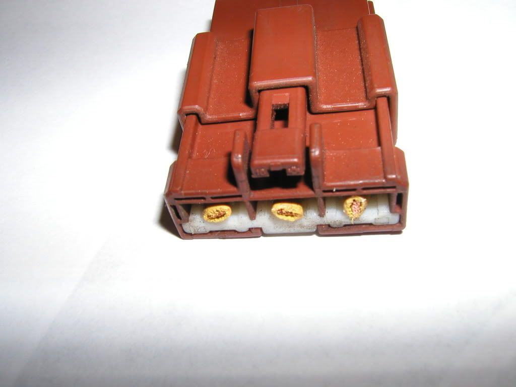
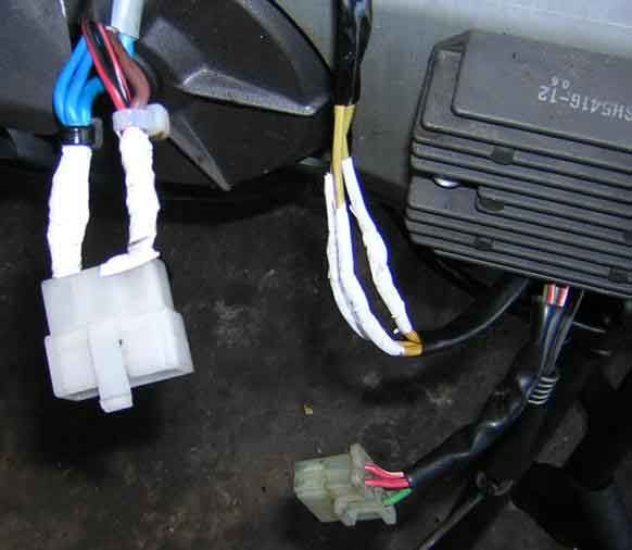
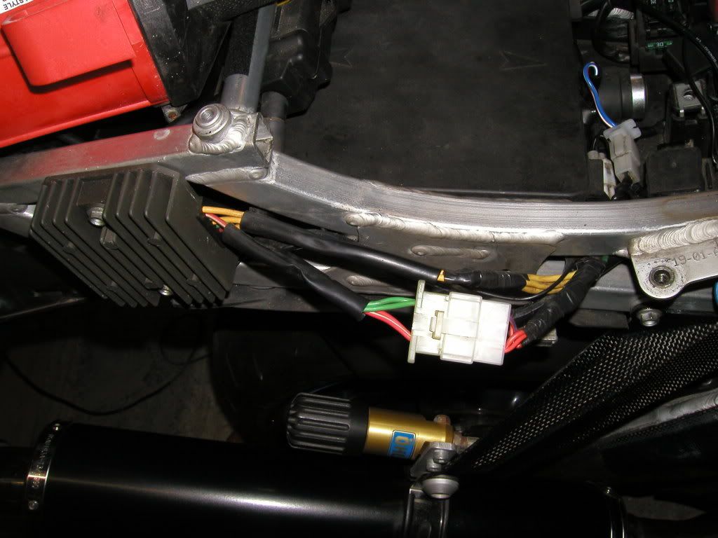
Cut the three thick yellow wires at the brown plug (As close to the plug as possible) and solder the connections as per the photos below.
The yellow wires may not quite be long enough once the brown connector has been removed, they do have some give in the loom end, give them a very gentle tug and you’ll gain another 2 cm of length this will be enough to allow you to make a good soldered connection.
The brown connector showing the yellow wires cut off flush.
Three yellow wires connected individually and insulated.
The three yellow wires bound by insulation tape.
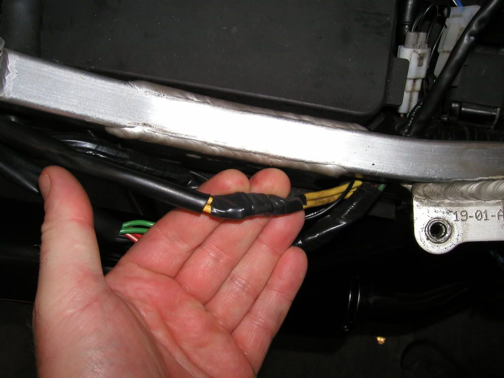
**NOTE** When cutting the three large yellow wires I did mine one at a time just in case they all got muddled up and for some unknown reason caused me charging problems.
Once all the yellow wires have been soldered make sure that they are well insulated from each other and the other wires in that area.
Don’t forget to cable tie the loom back to the frame once you’ve finished. (Mine wasn’t at this stage)
Wiring Modification Part 2
This part involves modifying the voltage regulator output wiring. Don’t worry this is the easy part.
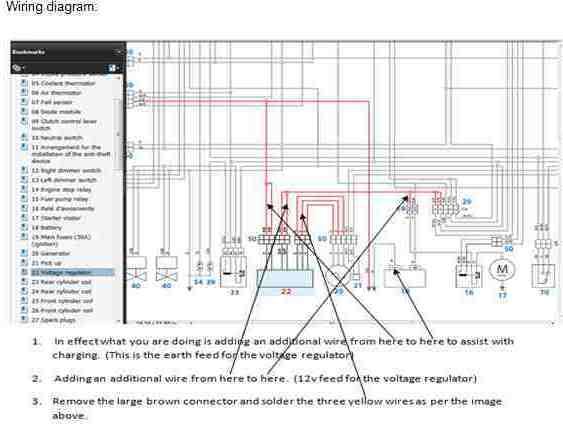
Just remember that all you are doing is adding in some extra wire to assist the existing wiring loom.
No fancy silicone wire is needed here, get some three core cable about 18” long, part of an old extension lead will do for this job. Strip off the outer casing so you have three separate wires and place to one side for now.
The first cable I added goes from the red with black tracer wire at the white plug to the red with black tracer wire at the 30A fuse block at the side of the battery. (Just near the starter solenoid)
(If you look closely you can just see the green wire I added disappear under the frame on its way to the 30A fuse holder)
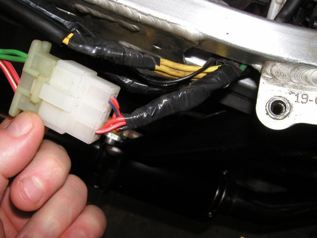
I like my wiring to look untouched and tidy so I threaded my additional wire up the black plastic sheath covering the loom that carries the red/black from the voltage regulator to the 30A fuse. Be warned this was a complete pain in the arse to do but I felt that it needed to be done on my bike.
This is the black sheath that I threaded my cable through.
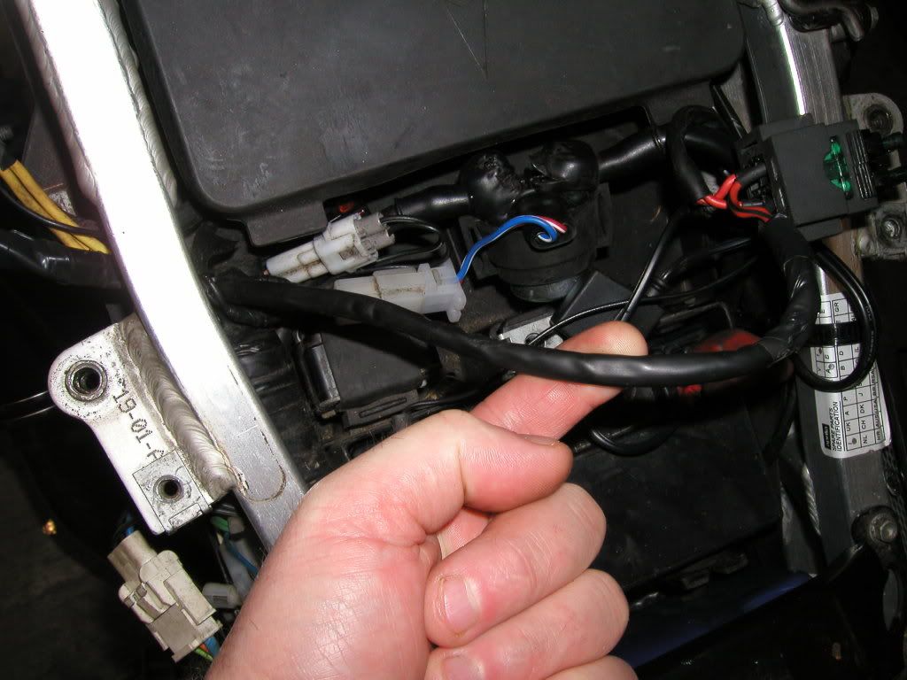
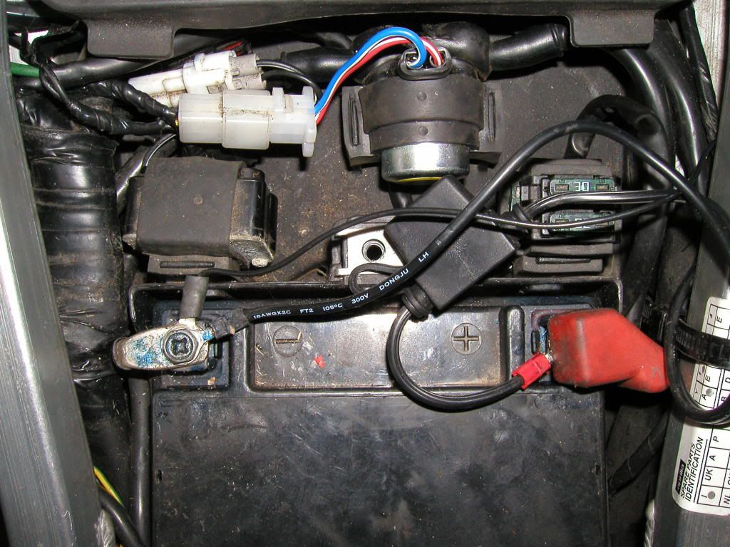
I also connected an extra earth cable for the voltage regulator, this goes from the red with blue tracer wire at the voltage regulator white plug to the negative terminal of the battery.
This additional earth wire can be soldered on to an existing connector at the battery negative terminal or in my case I added a ring terminal to the end of the cable and secured it to the battery terminal that way.
Again, just use one of those strands of wire stripped out of your three core cable you acquired earlier.
The finished product, you’d never know that I had been in there, would you?
Summary
Before I carried out this modification I had 13.80 Volts at the battery, tested using my Fluke. (Note, the dash voltage read at 12.2 Volts)
After the modifications I had 14.2 Volts at the battery, tested using my Fluke. (Note, the dash voltage read 13.2 volts)
All voltage readings were taken with the engine idling and no ancillaries activated.
As you can see not much of a gain in voltage at the battery but I now feel assured that my charging circuit is in tip top condition.
Please feel free to ask if you have any questions.
Wiring diagram:
