Since I provide Eproms I would like to help fitting them.
Here is a how to.
If you do it like in the movie there is a big change the Eprom will die of statics.

Look at the pictures and it explains itself.
Here we have the ECU.
Unscrew the 4 screws and lift up the lid
This is what it looks like inside.
This example is an Aprilia aftermarket RSV Titanium Eprom which comes with a descramble foot.
You have to take the out as well!!!
As you can see there is a notch on the white foot and on the Eprom.
They must match!!
By taking a piece of plastic and toughing the central heating first you lower the change of static electricity ruining the Eprom.
Lift one side up just a bit.
Then the other side.
Repeat this until the Eprom will come loose.
Now take your new Eprom and put it on the white Eprom foot.
Watch the notch !!
Put in one side only.
The other side will look like this.
Now push with your thumb on the side of the Eprom and push it to the side so all pins line up.
Or use the plastic tool to push each pin in while applying little pressure on top of the Eprom.
Now that's done screw the lit back together.
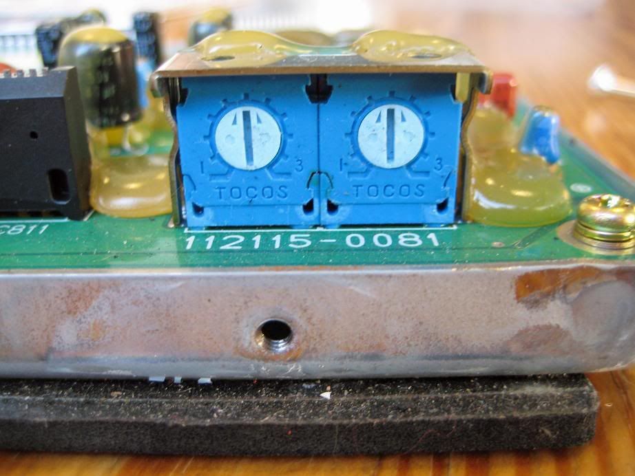
Adjust the trim pots to 12 o clock.
Put the connectors back in and put on the contact to hear if the fuel pump runs.
If not there is a problem.
Here are examples of a descramble board.
Mine comes without is since my software is not scrambled.
Hope this helps.
DrRossi


